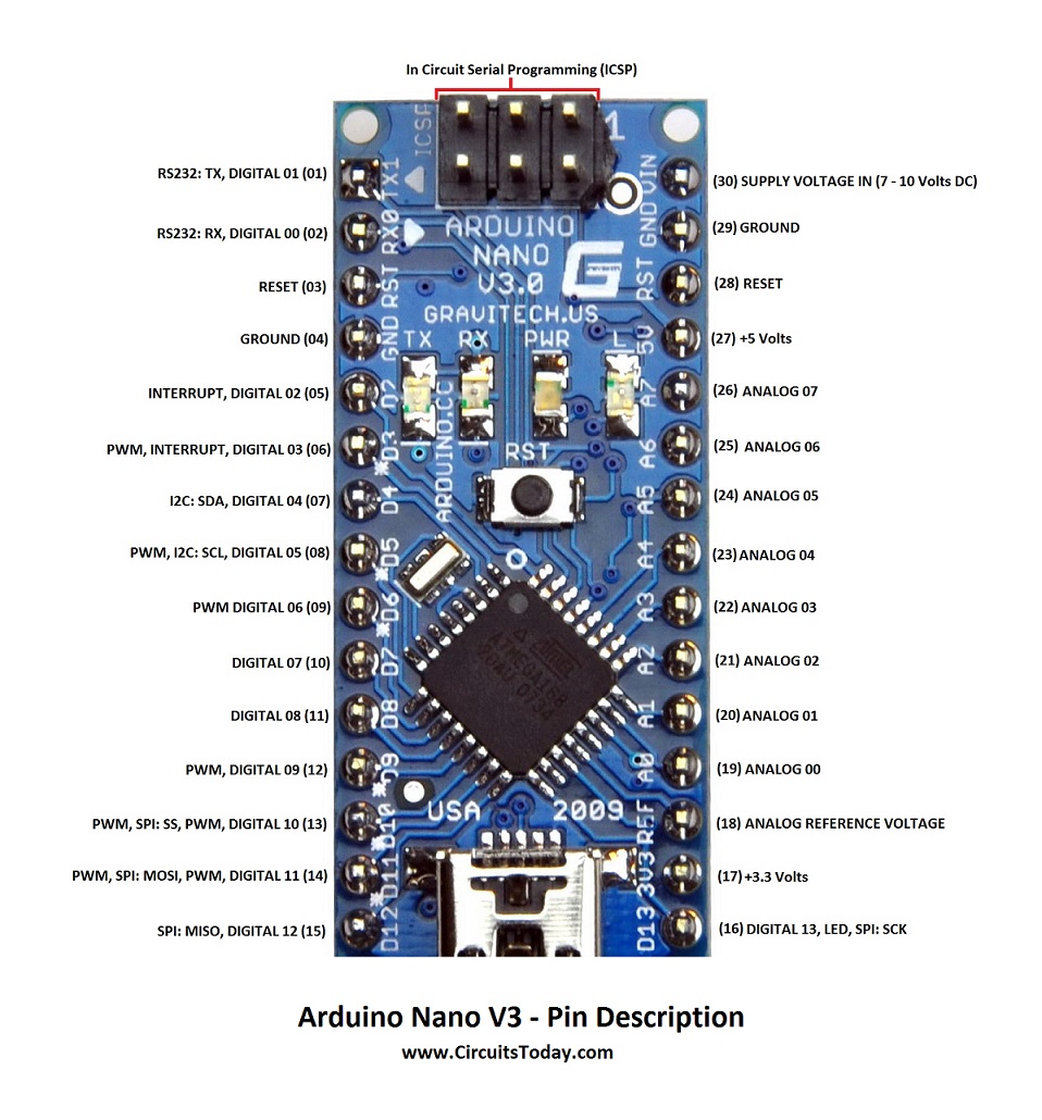
Because of substantial price difference, many users are using Chinese clones of the genuine Arduino development boards. Although in most cases the functionality is similar or even identical to the original, there may be some differences. Unfortunately, quite often there is virtually no schematics, datasheets or detail description available. This is a case for a Chinese clones of the Arduino Nano R3 board as well.
Component Required: (1) x Elegoo Mega2560 R3 (1) x DHT11 Temperature and Humidity module (3) x F-M wires (Female to Male DuPont wires) Page 92 excellent long-term stability. The sensor includes a resistive sense of wet components and a NTC temperature measurement devices, and connects with a high-performance 8-bit microcontroller. Arduino mega 2560 pinout diagram pdf wire data. This is the main controller used to program and run task for the system. The chip used in arduino 2560. Below is the pin mapping for the atmega2560. Pines pinout due arduino uno mega atmega 328 644 arduino mega 2560 pinout tft not working difference between arduino. Learn how to use potentiometer with Arduino, how potentiometer works, how to connect potentiometer to Arduino, how to code for potentiometer using Arduino, how to program Arduino step by step. The detail instruction, code, wiring diagram, video tutorial, line-by-line code explanation are provided to help you quickly get started with Arduino. Find this and other Arduino tutorials on.
After some research, measurements and detail inspection of the boards I was able to get together all circuits. Below you will find both schematics and few technical comments to the Nano CH340 R3 development board. I have purchased several Nano 3.0 CH340 clones in different orders from several Asian vendors and they are all almost identical, so it seems that this type of the Nano 3.0 board is widely used.
Nano CH340 R3 board description
The Nano CH340 R3 board is similar to the genunine Arduino Nano board, described on the original Arduino website here . The board uses same type of Mini-B USB connector, same side connectors and 6-pin SPI connector, as well as the Atmel ATmega328P microcontroller in the 32-TQFP package. There are also 4 LEDs – Power LED, LED connected to digital output pin D13, and two LEDs showing status of the RxD and TxD communication lines.
To provide +5.0 V Vcc power supply, the board uses LM1117-5.0 SOT-223 linear stabilizer 5.0 V (compared to original UA78M05), with slightly higher current (800 mA vs. 500 mA of original UA78M05) and lower drop-out voltage (typ. 1.2 V vs. 2.0 V for UA78M05).

To facilitate the USB communication and to provide 3.3 V output, the board uses USB communication circuit CH340 in SOP-16 package (instead of FT232RL used on the genuine Nano R3 board), manufactured by several Chinese companies. The CH340 IC requires installation of driver software, which was covered and explained many times already, so I will not repeat this information. With installed driver, communication with Arduino (IDE) is clear and straightforward.
To switch between VIN power supply (6-12 V) and USB power supply, the board includes a Schottky diode with low forward voltage. Most of the boards I got seems to be using the Vishay Semi SD101CWS diode (Vf 0.6 – 0.8 V at 20 mA, S4 SMD marking code).
Differences to the genuine Arduino Nano R3 board
- For both ATmega328P and CH340, the board uses 3-pin SMD ceramic resonators with internal load capacitors, so no external capacitors for oscilating circuit are needed not they are used (although there are soldering pads provided next to the CH340 resonator).
- Rx and Tx LEDs are connected directly to the ATmega328P outputs PD0 and PD1, so keep that in mind in case those two pins will be used for something else than USB communication (on genuine Nano R3 board the Rx and Tx LEDs are driven by additional outputs on the FT232RL chip).
- The CH340 chip includes the 3.3 V LDO voltage regulator, which can supply up to 25 mA. There is no refence in the original CH340 datasheet or elswhere on the internet, so I measured the supplied 3V3 voltage directly.
With no load, the 3V3 pin voltage was 3.28 V. With load up to 25 mA the voltage dropped to 3.18-3.22 V (on different boards); however at 30 mA load the voltage dropped to 3.10 V and further to 2.85 V at 40 mA.
Schematics
Elegoo Nano Pinout Diagram
Finally, below is a link to schematics of the Nano CH340 R3 board in pdf. Feel to copy and share as you like, providing you will attach the copyright info “copyright actrl.cz”. Please note that previously there was an error in connection of pins 2&3 on CH340 – on rev. 1 of the file this is corrected (CH340 (3) Rx pin is connected to Tx LED and (31) Tx pin of ATMega 328P, while CH340 (2) Tx pin is connected to Rx LED and (30) Rx pin of ATMega 328P – thanks Jindra Fučík to pointing this out).